|
Project Photos Battel Engineering, Inc. |
Click on an
image for a larger view and description |
|||
 |
 |
 |
 |
|
| 1. Steve gave a workshop on high voltage engineering on April 2-3, 2012 with a follow-on 2 days on October 22-23 2012 | 2. See Steve, with Rob Manning (JPL) and Glenn Reeves (JPL) give their University of Michigan “3 Amigos” talk on YouTube |
3. PIXL X-ray Head Including the 30 kV High Voltage Module |
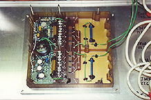
4. LV Control Module for PIXL X-Ray Head | |
 |
 |
 |
 |
|
| 5. SAM Analog Electronics (AE) | 66. View of Valve-Heater Module as part of integrated SAM Analog Electronics |
7.
SAM Valve-Heater Module flight model prior to AE integration |
8.
SAM Power Supply Module flight model |
|
 |
 |
 |
 |
|
|
9.
SAM Power Supply Module flight model |
10. Power Supply Control Assembly | 11. Power Supply MosFet Assembly |
12.
SAM Pyrolysis-Temperature Module flight model |
|
 |
 |
|||
|
13.
SAM Filament-Bias Module flight model |
14. SAM High Voltage Module (HVM) | |||
 |
 |
 |
 |
|
| 15. Demonstration of a Simple 40,000 Volt Faraday Cup Modulator Concept | 16. Testing a 50,000 Volt Distributed Reluctance Transformer | 17. 50,000 Volt Vacuum Isolated Transformer Concept | 18. Testing Vacuum Isolated Transformer Concept in Air | |
 |
 |
 |
 |
|
| 19. X-Ray Tube Beam Blanking Using a Retarding Potential | 20. 20,000 Volt Filament Transformer Using Traditional Dielectric Isolation |
21.
170 kV High Voltage Module at Several Stages of Assembly |
22.
500 kV Load and 100,000: 1 Voltage Divider |
|
 |
 |
 |
 |
|
|
23.
100,000: 1 Voltage Divider in Pre-Assembled State |
24.
Arc Test Setups for Europa Clipper Mission |
25. 7000 Volt “VapeArc” Generator | 26. Magnet Wire DWV and Partial Discharge Testing of Magnet Wire for Europa Clipper | |
 |
 |
 |
 |
|
|
27.
More Breakdown Testing for Europa Clipper |
28. Coaxial Cable Arc Sensitivity Testing for Europa Clipper |
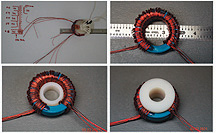
29. Winding Secondary Bobbins for High Voltage Transformers |
30. A Single-Section Prototype High Voltage Multiplier for a 60 kV System |
|
 |
 |
 |
 |
|
| 31. The 60 kV Drive Transformer and Oscillator Prototype Under Test |
32.
100 kV Load and Voltage Divider for Testing the 60,000 Volt Prototype High Voltage System |
33.
50 kV Voltage Isolator for the SPICES Instrument |
34. 50 kV High Voltage Isolators in the Salad Bowl” Test Setup |
|
 |
 |
 |
 |
|
| 35. A Test Surprise |
36.
DraMS Instrument Filament Control in Closed Loop Test |
37. RTW X-Ray Tube Under Test | 38. 25 kV Closed-Loop Load Simulator | |
 |
 |
 |
 |
|
|
39.
“Dead Simple” Voltage Bus Ground Isolator |
40. Orbion PCU Brassboard 2 Under Test |
41.
High Voltage Transformer Testing for the SWOT Mission |
42. Ringing Choke Bias Supply | |
 |
 |
 |
 |
|
|
43. RF Interference Testing a CubeSat for Spire Global. |
44.
Special Assistant Kayli Battel with a CubeSat in the lab |
45. Satellite Solar Array Shunt System |
46. 400 Watt Power Unit for a Miniaturized Hall Effect Thruster |
|
 |
 |
 |
 |
|
| 47. High Voltage Opto-Coupler Partial Discharge Testing |
48.
High Voltage Cable Noise and Breakdown Testing |
49. EN-11 High Voltage Life Test |
50. PicSpec Brassboard -100,000 Volt Power Module |
|
 |
 |
 |
 |
|
|
51. PicSpec Brassboard Power Electronics and Control Module |
52. Progressive Stages of Build-up for the PIXL High Voltage Module |
53.Potted PIXL High Voltage Module | 54. PIXL X-Ray Tube Test Module | |
 |
 |
|||
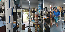
| 55. Progression of PIXL High Voltage Module Test Setups |
56. Thermal Test Setup for PIXL Brassboard Hardware |
|||
 |
 |
 |
 |
|
| 5757.
100 kilovolt high voltage power supply prototype under test for the PicSpec instrument |
58.
An early version of the -100 kilovolt high voltage power supply prototype |
5959.
35 kilovolt isolation transformer for the PicSpec instrument |
60. The PIXL instrument brassboard 28,000 volt power supply under development for JPL |
|
 |
 |
 |
 |
|
|
61.
The PIXL high voltage power supply from picture 16 set up for its life test |
62. Close up view of the development version of the PIXL high voltage module |
63.
Brassboard version of the PIXL high voltage system |
64.
The PIXL x-ray tube built up into a non-flight assembly for testing |
|
 |
 |
 |
 |
|
| 65. MOMA breadboard testing of miniaturized power supply | 66. The MOMA project Filament-Bias (FB) module |
67.
A closer look at the FB module discussed in picture 22 |
68. The MOMA Power-High Voltage (PH) module | |
 |
 |
 |
 |
|
|
69.
The integrated Secondary Electronics Box (SEB) module |
70.
The FB (right side) and PH modules side-by-side |
71.
Bench testing of the FB and PH modules |
72. MOMA Power Supply (PS) brassboard for testing |
|
 |
 |
 |
 |
|
|
73.
MOMA test simulator with a pair of flight-like filaments |
74.
MOMA Filament control and bias testing |
75. MOMA special cables and connectors testing |
76. MOMA couplers and magnetic devices testing |
|
 |
 |
 |
 |
|
|
77.
MAVEN NGIMS instrument power supply testing |
78.
MAVEN FM IUVS high voltage power supply |
79.
MAVEN FM IUVS high voltage power supply under test |
80. MAVEN FM IUVS high voltage power supply under test for output noise |
|
 |
 |
 |
.jpg) |
|
| 81. PC board dielectric breakdown measurements | 82.
Picture of fully assembled 25,000 x-ray high voltage power supply prototype |
83.
Final bench test for assembled 25,000 x-ray high voltage power supply prototype |
84. The SAM (Surface Analysis at Mars) instrument undergoing conducted susceptibility testing | |
 " " |
.jpg) |
 |
 |
|
| 85. The dual LISN (Line Impedance Stabilization Network) | 86. SAM EMC testing at Goddard |
87.
Final bench test of testing of the 25,000 x-ray high voltage power supply |
88. 25,000 x-ray high voltage power supply | |
 |
 |
 |
 |
|
| 89. Breadboard testing of 25,000 volt x-ray power supply |
90.
High voltage module used with the 25,000 x-ray high voltage power supply |
91.
LADEE flight PS/HV (Power Supply and High Voltage) module |
92. Top side view of the LADEE Engineering model PS/HV module | |
 |
 |
 |
 |
|
|
93.
Junior assistant Kayli Battel helping with testing |
94.
LADEE PS/HV Engineering being set up |
95.
LADEE PS/HV Engineering mounted on copper bench |
96. LADEE PS/HV Engineering in special noise testing configuration |
|
 |
 |
 |
 |
|
|
97.
LADEE PS/HV Engineering being tested for radiated magnetic signature |
98.
Opto-coupler test setup for LOKI tether HVPS |
99.
Infrared LED test fixture for qualification of LED's |
100. Battel Engineering's Rocket Squad pointing their rockets skyward | |
 |
 |
 |
 |
|
|
101. LADEE and MAVEN flight and engineering magnetic parts |
102. LADEE and MAVEN magnetic parts in thermal oven |
103. Main transformer test fixture for LADEE and MAVEN flight devices |
104. Main transformer test fixture for LADEE and MAVEN flight devices |
|
 |
 |
 |
 |
|
| 105. Steve at his "other job" | 106. Spare AIM high voltage power supply being tested |
107. Assistants Kayli and David working on the water manifold |
108. Custom heat exchanger in operation at "Casa Battel" |
|
 |
 |
 |
 |
|
| 109. Wideband RF amplifier under development | 110. First development board for a high radiation tolerance power supply |
111. SAM High Voltage Multiplier Assembly Test Setup |
112. MMS High Voltage Opto-Coupler Test |
|
 |
 |
 |
 |
|
|
113. Vacuum Tube X-Ray Source Modulator |
114. High Voltage Cable Noise Coupling Test |
115. 25,000 Volt X-Ray Source Power Supply Under Test |
116. 500 Watt Dynamic Tether High Voltage Power Supply |
|
 |
 |
 |
 |
|
|
117. Tether Power Supply PWM Drive Section |
118. Close-up of Tether High Voltage Drive Section |
119. Close-up of Tether High Voltage Modulator | 120. Tether Floating Drive System Under Preliminary Test | |
 |
 |
 |
 |
|
| 121. Tether System Radiated EMC Test | 122. 2000 Watt Tether Load |
123.
Mars Atmosphere Breakdown Simulator |
124. 25,000 Volt High Voltage System | |
 |
 |
 |
 |
|
| 125. 25,000 Volts Power Supply Under Test |
126.
Mars-Phoenix TEGA Brassboard Under Test |
127.
SAM Emission Control Simulator Under Test |
128. High Voltage Feedback Tuning | |
 |
 |
 |
 |
|
|
129.
High Voltage Opto-Coupler Screening Setup |
130.
Chemin Filament Simulator Under Test |
131. Chemin Filament Simulator During Assembly | 132. Chemin Filament Simulator During Assembly | |
 |
 |
 |
 |
|
|
133.
JADE 11,000 Volt High Voltage Power Supply Demo. Breadboard |
134. JADE High Voltage Modulator Development |
135.
JADE High Voltage Component Life Testing |
136.
SAM Analog Electronics (AE) Bench Testing |
|
 |
 |
 |
 |
|
|
137.
SAM Analog Electronics (AE) Thermal Testing |
138.
SAM PS Module Configured for Thermal Testing |
139. PS Control Assembly Bench Test |
140.
SAM Pyrolysis-Temperature Module Bench Test |
|
 |
 |
 |
 |
|
|
141.
SAM Filament-Bias Module on Inspection Bench |
142.
SAM Filament-Bias Module Bench Test |
143.
Combined FB-PT Module Bench Test |
144. Combined FB-PT Module Thermal Test |
|
 |
 |
 |
 |
|
|
145.
SAM High Voltage Module (HVM) Bench Test |
146.
SAM High Voltage Connector Testing |
147. SAM Magnetics Screening | 148. SAM Transformer Screening | |
 |
 |
 |
 |
|
| 149. SAM Inductor Saturation Testing |
150. Partial Discharge Test Setup Calibration |
151. Piezo-Electric Test Setup | 152. Piezo-Electric Test Setup | |
 |
 |
 |
 |
|
| 153. Piezo-Electric Test Setup |
154.
Lab Assistant in Robotics Laboratory |
155. SAM Brassboard PS Test Setup | 156. SAM Brassboard PS Test Setup | |
 |
 |
 |
 |
|
| 157. 400 MHz Slot Antenna Test | 158. TEGA-EGA Flight Model Face View | 1591. TEGA-EGA High Voltage Umbilical |
160.
TEGA-EGA Low Voltage Module Interior View |
|
 |
 |
 |
 |
|
|
161. TEGA-EGA High Voltage Module Bottom View |
162. TEGA High Voltage Module Top View |
163. Top View of TEGA Emission Control Board |
164. TEGA HVM Functional Bench Test Setup |
|
 |
 |
 |
 |
|
|
165. TEGA HVM in Thermal Test Chamber |
166. TEGA LVM in Bench Test Setup |
167. Integrated TEGA Flight Model in Functional Test |
168. TEGA High Voltage Transformer Qualification Setup | |
 |
 |
 |
 |
|
| 169. TEGA High Voltage Transformer Stepped-Voltage Testing |
170. TEGA Power Supply Breadboard Test |
171. TEGA Integrated High Voltage Breadboard Test |
172. TEGA High Voltage Breadboard Test |
|
 |
 |
 |
 |
|
| 173. TEGA Filament/Emission Control Breadboard Test Setup |
174. TEGA High Voltage Breadboard Test Setup |
175. TEGA Emission Control Test with Real Filament |
176. Bench Test of Actual TEGA Filament |
|
 |
 |
 |
 |
|
| 177. UHF Filter Test | 178. High Voltage Test Setup | <179. AIM-CIP High Voltage Power Supply | 180. AIM-CIP High Voltage Power Supply, Bottom View | |
 |
 |
 |
18 |
|
|
181. Control Loop Testing of AIM-CIP HVPS |
182. Top View of Huygens GCMS Instrument |
183. Side View of Huygens GCMS Electronics |
184. Side View of Huygens GCMS Electronics |
|
 |
 |
 |
 |
|
|
185. GALEX Engineering Model High Voltage Power Supply |
186. GALEX Engineering Model Low Voltage Power Supply |
187. GP-B Aft Power Unit | 188. GP-B Aft Power Unit, Back Side | |
 |
 |
 |
 |
|
| 189. APU in Bench Test Setup | 190. GP-B Forward Regulator Module |
191. Rosetta IES High Voltage Power Supply with Control Module |
192. Interior View of IES HVPS | |
 |
 |
 |
 |
|
| 193. IES HVPS in Test Fixture |
194. Hubble Spectrograph Power Converter |
195. 2000 Watt Battery Charge Controller |
196. QuickToms PMIU2 Power Converter Breadboard |
|
 |
 |
 |
 |
|
| 197. PMIU2 Configured for Test |
199. 2000 Watt High Voltage Breadboard |
199. SAM Thermo-Electric Cooler Test Setup |
200. SAM Bulb Filament Simulator | |
 |
 |
 |
 |
|
|
201. UC Berkeley Antenna Calibration Setup |
202. IMAGE Spacecraft E-Field Mockup | 203. The “Bird Cage” | 204. The “Big Box” | |
 |
||||
| 205. Testing Inside the “Big Box” | ||||
Images © Steve Battel, Battel Engineering, Inc. All rights reserved. |
||||